Experimental database for detecting and diagnosing rotor broken bar in a three-phase induction motor.
- Citation Author(s):
-
Aline Elly Treml (Western Parana State University (UNIOESTE) Foz do Iguaçu, Brazil)Rogério Andrade Flauzino (University of São Paulo (USP) Sao Carlos, Brazil)Marcelo Suetake (Federal University of São Carlos (UFSCAR), Brazil)Narco Afonso Ravazzoli Maciejewski (University of Sao Paulo (USP) Sao Carlos, Brazil)
- Submitted by:
- NARCO AFONSO MACIEJEWSKI
- Last updated:
- DOI:
- 10.21227/fmnm-bn95
- Data Format:
- Links:
 27547 views
- Categories:
- Keywords:
Abstract
The data set contains electrical and mechanical signals from experiments on three-phase induction motors. The experimental tests were carried out for different mechanical loads on the induction motor axis and different severities of broken bar defects in the motor rotor, including data regarding the rotor without defects. Ten repetitions were performed for each experimental condition.
Instructions:
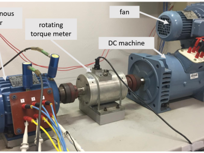
Experimental Setup:
The experimental workbench consists of a three-phase induction motor coupled with a direct-current machine, which works as a generator simulating the load torque, connected by a shaft containing a rotary torque wrench.
- Induction motor: 1hp, 220V/380V, 3.02A/1.75A, 4 poles, 60 Hz, with a nominal torque of 4.1 Nm and a rated speed of 1715 rpm. The rotor is of the squirrel cage type composed of 34 bars.
- Load torque: is adjusted by varying the field winding voltage of direct current generator. A single-phase voltage variator with a filtered full-bridge rectifier is used for the purpose. An induction motor was tested under 12.5, 25, 37.5, 50, 62.5, 75, 87.5 and 100% of full load.
- Broken rotor bar: to simulate the failure on the three-phase induction motor's rotor, it was necessary to drill the rotor. The rupture rotor bars are generally adjacent to the first rotor bar, 4 rotors have been tested, the first with a break bar, the second with two adjacent broken bars, and so on rotor containing four bars adjacent broken.
Monitoring condition:
All signals were sampled at the same time for 18 seconds for each loading condition and ten repetitions were performed from transient to steady state of the induction motor.
- mechanical signals: five axial accelerometers were used simultaneously, with a sensitivity of 10 mV/mm/s, frequency range from 5 to 2000Hz and stainless steel housing, allowing vibration measurements in both drive end (DE) and non-drive end (NDE) sides of the motor, axially or radially, in the horizontal or vertical directions.
- electrical signals: the currents were measured by alternating current probes, which correspond to precision meters, with a capacity of up to 50ARMS, with an output voltage of 10 mV/A, corresponding to the Yokogawa 96033 model. The voltages were measured directly at the induction terminals using voltage points of the oscilloscope and the manufacturer Yokogawa.
Data Set Overview:
- Three-phase Voltage
- Three-phase Current
- Five Vibration Signals
Acknowledgements:
The database was acquired in the Laboratory of Intelligent Automation of Processes and Systems and Laboratory of Intelligent Control of Electrical Machines, School of Engineering of São Carlos of the University of São Paulo (USP), Brazil.


In reply to Hi Authors, by Pavol Mulinka
In reply to How much is the sampling by Yongtao Zhou
In reply to I figured it out as: by Stephan Tjaden
In reply to I figured it out as: by Stephan Tjaden
In reply to The corresponding research by Bora Eryilmaz
What articles indicate that the current frequency is collected at 50 kHz? How do you know that the samples are approximately 20 seconds long without knowing the sampling rate?
Thank you very much.
What is the Resolution of aquisition system? 16 bits, 14 bits, ...?
I used Excel to plot the graph, but the three-phase voltage has no phase difference. Why?