OOK Modulated Dataset
- Citation Author(s):
-
Mariam Abdullah (Terahertz Engineering Laboratory, The University of Adelaide)Estrid He (School of Computing Technologies, RMIT University)Mohamed Shehata (School of Engineering, RMIT University)Ke Wang (School of Engineering, RMIT University)Withawat Withayachumnankul (Terahertz Engineering Laboratory, The University of Adelaide)
- Submitted by:
- Mariam Abdullah
- Last updated:
- DOI:
- 10.21227/k664-m285
- Data Format:
 293 views
- Categories:
- Keywords:
Abstract
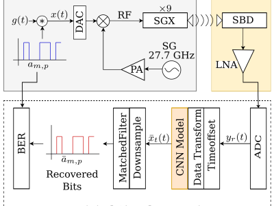
The terahertz communications band in the 252 to325 GHz range has been recently explored for its potential to meet the stringent requirements for the emerging sixth generation of wireless communications. However, there are several challenges including noise and nonlinearity that hinder efficient implementations. We aim to address this limitation in terahertz communications through convolutional neural networks (CNN) enhanced by the domain knowledge from traditional Volterra filters. This dataset contains the time-domain data used to train a CNN model used for nonlinearity compensation in a terahertz communications system. The proposed model achieves a 2.28 dB improvement
in total harmonic distortion (THD) compared to the Volterra equalizing method also shows a significant SNR improvement.
Instructions:
The dataset contains the transmitted and received signal from the microwave communication setup. The transmitted data consists of PRBS data which was pulse shaped using a Root Raised Cosine filter (RRC) and was modulated using OOK using a terahertz carrier. A leading clock consisting of 4 'on' and 4'off' symbols is appended to the transmitted data and used to synchronize the transmitted and received data. The data is collected from the receiver side at various distances ranging from 0cm to 10cm.
The transmitted files consist of several periods of the received signal and must be synchronized with the transmitted signal for labels and BER calculations. To synchronize the signal the following steps must be followed:
Resample the received signal to match the sampling rate of the transmitted signal. An oversampling factor of 4 is used
Generate the clock patterns which consists of 100 samples of leading zeros followed by the on-off clock pattern followed by an additional 100 samples of training zeros.
Utilize cross correlation to identify the beginning of the period