5G CFR/CSI dataset for wireless channel parameter estimation, array calibration, and indoor positioning
- Citation Author(s):
-
Mengguan Pan
(Pervasive Communication Research Center, Purple Mountain Laboratories, Nanjing 211111, China)
Shengheng Liu(School of Information Science and Engineering, Southeast University, Nanjing 210096, China)
Peng Liu(College of Electronic and Information Engineering, Nanjing University of Aeronautics and Astronautics, Nanjing 211106, China)
Wangdong Qi(School of Information Science and Engineering, Southeast University, Nanjing 210096, China)
Yongming Huang(School of Information Science and Engineering, Southeast University, Nanjing 210096, China)
Wang Zheng(Pervasive Communication Research Center, Purple Mountain Laboratories, Nanjing 211111, China)
Qihui Wu (College of Electronic and Information Engineering, Nanjing University of Aeronautics and Astronautics, Nanjing 211106, China) - Submitted by:
- Mengguan Pan
- Last updated:
- DOI:
- 10.21227/k2f0-k132
- Data Format:
Abstract
Channel frequency response (CFR) dataset used for "In-Situ Calibration of Antenna Arrays for Positioning With 5G Networks" paper (IEEE Transactions on Microwave Theory and Techniques, in print, doi: 10.1109/TMTT.2023.3256532, preprint link: https://arxiv.org/abs/2303.04470).
Since the CFR of the wireless channel, which is also known as the channel state information (CSI) in many cellular or Wi-Fi positioning literature, contains the angle and delay information of both the direct path and reflected paths, we believe the following research fields can benefit from this dataset:
1. direction-of-arrival (DOA) estimation and array calibration,
2. time-of-arrival (TOA) estimation,
3. joint parameter estimation for indoor positioning and navigation,
4. line-of-sight (LOS) and non-line-of-sight (NLOS) identifications,
5. wireless channel parameters estimation.
We use a baseband unit (BBU), a four-channel picocell sub-6GHz remote radio unit (RRU), and a user terminal (UT) to collect the wireless CFRs, all of them are commercial off-the-shelf products with 5G R16 specification supported. The 5G UT with a single omnidirectional cylindrical antenna is mounted on an autonomous vehicle, which communicates to the gNB and generates the ground-truth locations with an accuracy of several centimeters. This CFR dataset is collected in an underground parking lot of an office building. During experiments, the UT is placed at 476 different locations in the area of [−35 m, 10 m] × [8 m, 33 m]. At each location, the uplink wireless channel is measured repetitively via transmitting a series of uplink sounding reference signal (UL-SRS) symbols and their corresponding CFR data are logged. Aside from CFR data from these 476 locations, other assisted measurement data, including the ground-truth locations of the UT, the six degrees of freedom (6-DoF) pose of the RRU, the locations of the dominant obstacles (i.e. the pillars) in the environment, are also provided.
Instructions:
Instructions for the dataset "5G CFR/CSI dataset for wireless channel parameter estimation, array calibration, and indoor positioning"
This dataset contains uplink channel frequency response (CFR) samples measured in a real indoor environment, as well as assisted measurement data, including the ground-truth locations of the user terminal (UT), the six degrees of freedom (6-DoF) pose of the radio remote unit (RRU), the locations of the dominant obstacles (i.e. the pillars) in the environment, etc.
Experimental environment
The CFR data is collected in an underground parking lot of an office building. The dimension of the experimental area is 45 m × 25 m. There are ten pillars amid this area, which block line-of-sight (LOS) propagation of wireless signals for certain relative geometries of the UT and RRU. The photograph of this experimental area is shown in the attached figure experiment_environment.jpg.
Experimental methodology
We deploy an RRU at the corner of the experimental area and place UT at 476 different locations in this area with an interval of about 1.5-2.5 m. At each location, the uplink wireless channel is measured repetitively via transmitting a series of uplink sounding reference signal (UL-SRS) symbols and their corresponding CFR data are logged. In this dataset, the number of UL-SRS symbols is 100 for each location.
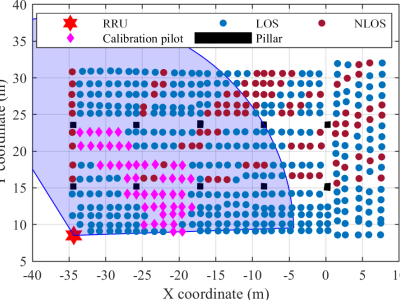
The attached file experiment_layout.png is a figure in our paper "In-situ Calibration of Antenna Arrays for Positioning with 5G Networks" which studies the in-situ calibration problem based on this dataset. It marks the 476 UT locations and uses different colors or markers for LOS positions, NLOS positions, and those used for deriving in-situ calibration coefficients.
System and signal parameters
- Carrier frequency: 4.85 GHz.
- Subcarrier spacing for UL-SRS: 30 kHz.
- Number of subcarriers for UL-SRS: 3264.
- UL-SRS pattern: Comb-two (i.e 1632 UL-SRS subcarriers are effective, with 60 kHz spacing).
- UL-SRS transmission bandwidth: 100 MHz.
- Sampling frequency: 122.88 MHz.
- UL-SRS temporal interval: 80 ms.
- Antenna array type: uniform linear array (ULA).
- Antenna element spacing: 3 cm.
Data format
The attached zip file includes:
- Raw CFR data:
cfr_XXX.mat, whereXXXis the location ID (001 to 476). Each mat file contains a three-dimensionalcfrmatrix (N_symbol(Number of UL-SRS symbols) *N_rx(Number of RRU receiving channels) *N_esc(Number of effective subcarriers)). - Ground-truth UE locations:
UE_location.xlsx, which contains the Cartesian coordinates (x, y, and z coordinates) of the 476 UE positions. - The 6-DoF pose of the RRU:
RRU_pose.xlsx, which contains the location (x, y, z) and pose (pitch, roll, yaw) of the RRU. - Location of the pillar:
pillar_corner_location.xlsx, which contains the coordinates of the corners of the 10 pillars in the experimental area measured by a total station. - The calibration coefficients for the RF channels of the RRU:
RRU_RF_channel_coefficient.mat, which contains a matrixrf_channel_coeff(N_rx(Number of RRU receiving channels) *N_esc(Number of effective subcarriers)). The n-th row of this matrix is the frequency response of the n-th RF channel of the RRU. Our prior work [1] presents methods for obtaining this RF channel calibration matrix. - A photo of the experimental area:
experiment_environment.jpg. - Illustration for the layout of data collection points:
experiment_layout.png.
References
[1] M. Pan, P. Liu, S. Liu, W. Qi, Y. Huang, X. You, X. Jia, and X. Li, “Efficient joint DOA and TOA estimation for indoor positioning with 5G picocell base stations,” IEEE Trans. Instrum. Meas., vol. 71, art. no. 8005219, pp. 1–19, Aug. 2022.
 2800 views




A research scholar looking for dataset. Kindly, help
I want to use this dataset to conduct research on TOA estimation.
HGreetings,
I would like to inquire about the Channel State Information (CSI), which is integrated within this dataset.
For any issues regarding the dataset, please contact my email panmengguan@outlook.com.