Interleaved Vienna Rectifier with Pulse Frequency Modulation - IVR-PFM
- Citation Author(s):
- Submitted by:
- Jefferson Wilhelm Meyer Soares
- Last updated:
- DOI:
- 10.21227/mm51-3z70
- Data Format:
 206 views
- Categories:
- Keywords:
Abstract
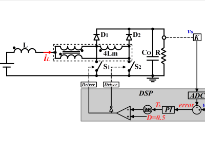
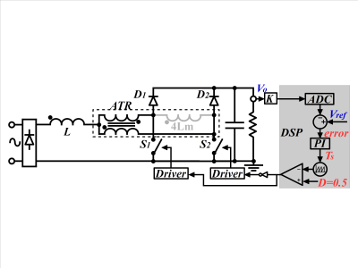
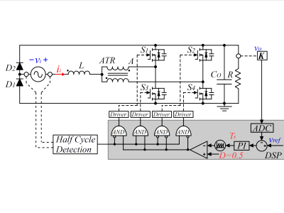
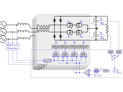
This dataset provides a simulation file for the Interleaved Vienna Rectifier with Pulse-Frequency Modulation (IVR-PFM) topology, developed for three-phase, three-wire applications. The simulation is designed for use with PSIM software and is configured to operate with a 220 V, 60 Hz line input voltage, delivering 3 kW of output power at 800 V. The IVR-PFM behaves as a resistive load at the input, with the equivalent resistance defined as Re = 4Lmfs, where Lm is the magnetizing inductance and fs is the switching frequency. The file includes a closed-loop implementation, which can be modified for open-loop tests by disabling the control loop and enabling the open-loop configuration.
Instructions:
IVR-PFM Simulation Dataset
This dataset contains a simulation file for the Interleaved Vienna Rectifier with Pulse-Frequency Modulation (IVR-PFM) topology. The simulation is prepared using PSIM software (ver. 2024) and is configured for nominal conditions, with options to modify the setup for specific analyses. Below, you will find details about the dataset configuration and instructions for its use.
1. Simulation Overview
- Input Voltage: 220 V, 60 Hz (three-phase, three-wire system)
- Output Power: 3 kW
- Output Voltage: 800 V
- Control Strategy: Closed-loop implementation, adjustable for open-loop operation
- Topology Behavior: The converter behaves as a resistive load at the input, with an equivalent resistance Re = 4Lmfs (Lm: magnetizing inductance; fs: switching frequency).
2. File Contents
The dataset includes the following file:
- IVR-PFM_Simulation.psimsch: The primary simulation file for PSIM software.
3. Instructions for Use
3.1 Closed-Loop Operation
The simulation is pre-configured for closed-loop control. In this mode, the converter operates under nominal conditions, maintaining the desired output power and voltage.
3.2 Open-Loop Operation
To perform open-loop tests:
- Disable the closed-loop circuitry in the simulation file.
- Enable the open-loop configuration circuitry
- Adjust the switching frequency to vary the input power level (lower switching frequency increases power conversion).
To facilitate the balance between input and output power in open-loop mode, enable the voltage source labeled "Vo" in the output stage and adjust its value if desirable.
4. Key Features of the IVR-PFM Topology
- Soft-switching operation with reduced stress on semiconductors.
- Continuous input current with resistive behavior.
- Simplified control strategy without the need for current sensing.
5. Additional Notes
The simulation is configured for nominal conditions, but users can modify parameters such as load, switching frequency, and control strategy to explore different operating scenarios.


