Datasets
Standard Dataset
Patch antennas characterization for enhanced microwave imaging
- Citation Author(s):
- Submitted by:
- Yuri Alvarez-Lopez
- Last updated:
- Wed, 01/08/2025 - 05:36
- DOI:
- 10.21227/erjz-db45
- Data Format:
- License:
 161 Views
- Categories:
- Keywords:
Abstract
This dataset corresponds to the measurements of two microstrip patch antennas, collected using the facility described in [1]. The available measurements contained within the dataset allow a complete characterization of the field radiated by these antennas. These fields can be introduced in enhanced microwave imaging algorithms that consider the field radiated by the transmitting and receiving antennas of the microwave imaging system [2] (modified Delay and Sum algorithm), [3] (modified Phase Shift Migration imaging algorithm). The patch antennas that are characterized are the ones presented in [4].
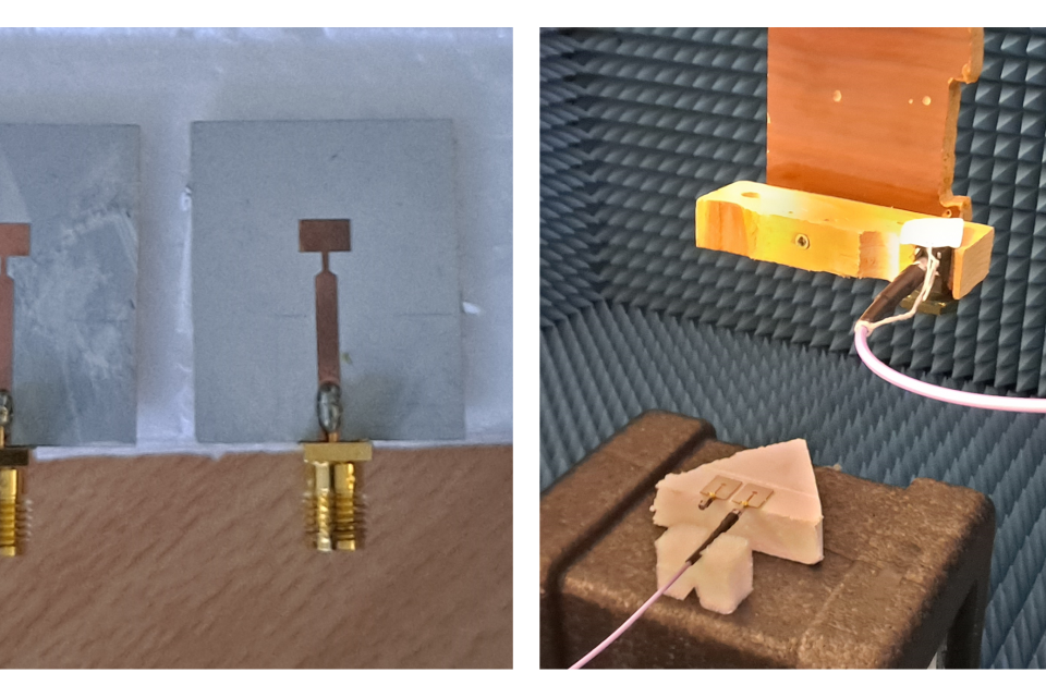
The files "Emeas_leftPatch_z30cm.zip" and "Emeas_rightPatch_z30cm.zip", correspond to the copolar component (Ex component) of the electric field radiated by the patch antennas (left and right as depicted in the figure “PictureDataset.png”). More precisely, it corresponds to the S21 parameter, which is proportional to the electric field radiated by the patch antenna.
Measurements were conducted within the frequency range from 22 GHz to 28 GHz, with a frequency step of 15 MHz. Measurements were collected on a domain of size Lx × Ly = 70 cm × 70 cm, discretized every δx,y = 5 mm (0.42 wavelengths at the center frequency of 25 GHz). The distance between the patch antenna (antenna under test) and the measurement plane was 30 cm. An Open-Ended Waveguide was used as probe antenna.
The measured electric field was backpropagated from the measurement plane to the patch antenna aperture plane using the backpropagation algorithm described in [5]. The electric fields on the aperture plane are provided in the files “Eap_leftPatch.zip” and “Eap_rightPatch.zip” for the left and right patch antennas, respectively. The aperture fields were calculated on a planar domain having the same size as the measurement plane, that is, Lx × Ly = 70 cm × 70 cm, and also discretized every δx,y = 5 mm.
[1] A. Arboleya, Y. Alvarez, and F. Las-Heras, “Millimeter and submillimeter planar measurement setup,” in 2013 IEEE Antennas and Propagation Society International Symposium (APSURSI), 2013, pp. 1–2.
[2] Y. Alvarez Lopez and F. Las-Heras, “On the use of an equivalent currents-based technique to improve electromagnetic imaging,” IEEE Transactions on Instrumentation and Measurement, vol. 71, pp. 8004113, 2022.
[3] Y. Alvarez López and F. Las-Heras Andrés, "Improved Methods for Fourier-based Microwave Imaging," Sensors, Vol. 23, pp. 9250, 2023.
[4] A. F. Berdasco, J. Laviada, M. E. de Cos Gómez and F. Las-Heras, “Performance Evaluation of Millimeter-Wave Wearable Antennas for Electronic Travel Aid,” in IEEE Transactions on Instrumentation and Measurement, vol. 72, pp. 1-10, 2023, Art no. 4507510, doi: 10.1109/TIM.2023.3320736.
[5] J. Hanfling, G. Borgiotti, and L. Kaplan, “The backward transform of the near field for reconstruction of aperture fields,” in 1979 Antennas and Prop. Society Intl. Symposium, vol. 17, 1979, pp. 764–767.
The dataset consists of the following files:
- “Eap_leftPatch.zip” ZIP file containing the copolar component (Ex component) of the backpropagated electric field on the aperture plane of the patch antenna (the left one as depicted in “PictureDataset.png”). The ZIP file has a single *.txt file.
- “Eap_rightPatch. zip” ZIP file containing the copolar component (Ex component) of the backpropagated electric field on the aperture plane of the patch antenna (the right one as depicted in “PictureDataset.png”). The ZIP file has a single *.txt file.
- “Emeas_leftPatch_z30cm. zip” ZIP file containing the field radiated by the patch antenna (left one as depicted in “PictureDataset.png”). More precisely, the S21 parameter, which is proportional to the measured electric field. The ZIP file has a single *.txt file.
- “Emeas_rightPatch_z30cm. zip” ZIP file containing the field radiated by the patch antenna (right one as depicted in “PictureDataset.png”). More precisely, the S21 parameter, which is proportional to the measured electric field. The ZIP file has a single *.txt file.
The submitted files are in *.txt format (compressed as ZIP files). These files can be accessed and visualized using the Matlab scripts described next:
- “PlotApertureFields.m” (compressed as ZIP file) Matlab script to import the “Eap_leftPatch.txt” and “Eap_rightPatch.txt” files (after decompressing the ZIP files) and plot the electric fields on the aperture plane.
- “PlotEmeas.m” (compressed as ZIP file) Matlab script to import the “Emeas_leftPatch_z30cm.txt” and “Emeas_rightPatch_z30cm.txt” files (after decompressing the ZIP files) and plot the measured electric field on the acquisition plane.
Dataset Files
- ZIP file containing the field radiated by the patch antenna (left one as depicted in “PictureDataset.png”). Emeas_leftPatch_z30cm.zip (140.83 MB)
- ZIP file containing the field radiated by the patch antenna (right one as depicted in “PictureDataset.png”). Emeas_rightPatch_z30cm.zip (141.80 MB)
- ZIP file containing the copolar component (Ex comp.) of the backpropagatedfield on the aperture plane of the left patch Eap_leftPatch.zip (86.46 MB)
- ZIP file containing the copolar component (Ex comp.) of the backpropagatedfield on the aperture plane of the right patch Eap_rightPatch.zip (86.47 MB)
- Matlab script to import the “Emeas_leftPatch_z30cm.txt” and “Emeas_rightPatch_z30cm.txt” files and plot the fields PlotEmeas.zip (720 bytes)
- Matlab script to import the “Eap_leftPatch.txt” and “Eap_rightPatch.txt” files and plot the aperture fields PlotApertureFields.zip (641 bytes)


