An Inductive Coupler Array for In-Motion Wireless Charging of Electric Vehicles
- Citation Author(s):
-
Vahid Zahiri Barsari
 (The University of Auckland)
Duleepa J. Thrimawithana (The University of Auckland)Grant A. Covic
(The University of Auckland)
(The University of Auckland)
Duleepa J. Thrimawithana (The University of Auckland)Grant A. Covic
(The University of Auckland)
- Submitted by:
- Vahid Zahiri Barsari
- Last updated:
- DOI:
- 10.21227/6q26-0f72
- Data Format:
- Research Article Link:
 542 views
- Categories:
- Keywords:
Abstract
An inductive power transfer (IPT) system is envisaged as the best solution to conveniently charge electric vehicles (EVs). While stationary IPT systems are becoming commercialized, significant research is being conducted to address the challenges related to dynamic IPT systems. Dynamic or in-motion IPT systems require a fully electrified roadway with embedded inductive couplers with accompanying circuitry. The large number of electronic components required, however, increases the system complexity, reducing the reliability and economic viability of dynamic IPT systems proposed to-date. This paper proposes a simple yet robust push-pull driven coupler array (PPCA), aiming to decrease the number of switches required to drive the in-road couplers. This paper is the first to report a configuration where only N+1 switches are required to independently energize N primary IPT couplers. Any number of couplers can be activated simultaneously in the array without proportionally increasing the current stress on the switches. A state-space model is developed and implemented in PLECS to investigate the efficiency and power transferred to an EV traveling over the proposed PPCA while considering the variation in the coupling and the self-inductances of the couplers. A 3.3 kW scaled prototype PPCA consisting of three primary couplers and two secondary couplers has been implemented to validate the performance of the proposed configuration.
Instructions:
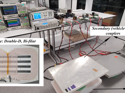
A video demonstration of a 3.3 kW scaled prototype of Push-Pull driven Coupler Array (PPCA).
This prototype consists of three primary couplers and two secondary couplers to validate the performance of the proposed configuration. The inverter consists of four Mosfets, which is capable of energizing and de-energizing three primary couplers independently through a proper phase-shift between the switches. Each primary coupler in the experiment is activated for one-second intervals to transfer 3.3 kW to the secondary coupler.
Paper's link on IEEE Xplore: https://ieeexplore.ieee.org/document/9353274
DOI: 10.1109/TPEL.2021.3058666