Datasets
Standard Dataset
Induction machine reverse and regenerating mode
- Citation Author(s):
- Submitted by:
- Marcin Morawiec
- Last updated:
- Tue, 03/19/2024 - 08:11
- DOI:
- 10.21227/mvfr-1y57
- Data Format:
- Research Article Link:
- License:
 179 Views
- Categories:
- Keywords:
Abstract
The unstable working points of the induction machine in a sensorless controller are commonly known problems. This paper proposes a new stabilization method for the model-based speed observer of an induction machine. Considering the proposed solution, the rotor speed can be reconstructed based on the mathematical model of a machine by using both adaptive and non-adaptive schemes. The presented method is generalized to the classical nonlinear system in the vector form and can be applied to induction machines. The Lyapunov theorem is used during the design procedure for stability purposes. The simulation and experimental studies are carried out for an induction machine adaptive and non-adaptive observer.
Description
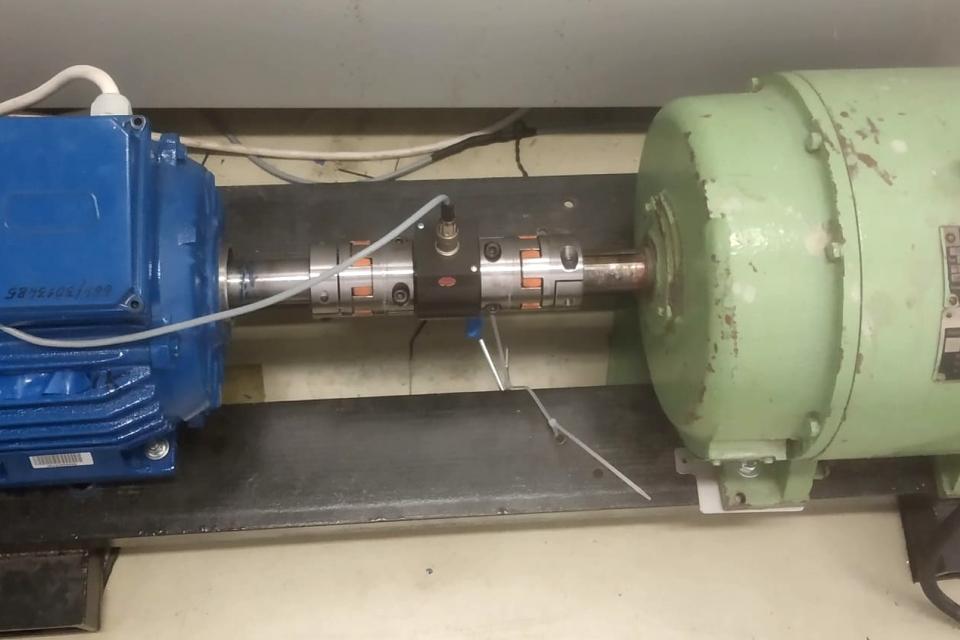
On the left side, the 5.5 kW induction machine (blue), coupled to the DC machine (green), is visible. The torque meter with the digital oscilloscope is installed in the middle. The signal from the torque meter is connected to the oscilloscope by using a voltage probe.
In this movie there is the machine reverse shown from 142 rpm to -142 rpm (0.1 to -0.1 p.u.). The ramp time was set to about 6s (from 0.1 to -0.1 p.u.). The load torque is about 25-27 Nm and it has constant value during this test.
- After 0 s the rotor speed is set to 0.1 p.u.
- After 1 s the load torque is turn on (it is increasing up to 25-27 Nm) - the motoring mode
- After 5 s the reference rotor speed is change to -0.1 p.u. (-142 rmp)
- After 10-11 s the rotor speed reaches the zero and it changes the sign (reverse)
- After 11 s machine works in the regenerating mode (the load torque is not changed)
- After 22 s the load torque is off.
Induction machine nominal parameters
Symbol | Quantity | Values |
RsN | stator resistance | 2.92 Ω/0.035 p.u |
RrN LmN Ls, Lr Lσ Pn In Un n f Ub=Un
Pb | rotor resistance magnetizing inductance stator and rotor inductance leakage inductance nominal power nominal stator current (Y) nominal stator voltage (Y) nominal rotor speed nominal frequency reference voltage reference current reference power | 3.36 Ω/0.032 p.u 0.422 H/1.95 p.u 0.439 H/2.04 p.u 0.017 H/0.09 p.u 5.5 kW 11 A 400 V 1430 rpm 50 Hz 400 V 19 A 7.6 kW |
More from this Author
Documentation
| Attachment | Size |
|---|---|
| 175.05 KB |


