Pressure Sensor
When producing bolts in a cold forging process, the pressure signals are recorded per cycle of forming a bolt. The dataset is collected from experiments of different failure modes of a forming machine. Two experiments were recorded in csv format for providing four failure modes, including core broken, cavity block, insufficient lubrication, and material out-of-specification, as well as one normal mode. The two experiments were performed in the same machine with different cavities and cores, and saved in Experimental Data for Modeling and Testing.
- Categories:
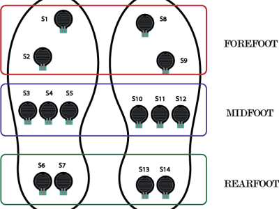
The pressure sensors are represented by black circles, which are located in the three zones of each foot. For the left foot: S1 and S2 cover the forefoot area. S3, S4, and S5 the midfoot area. S6 and S7 the rearfoot or heel area. Similarly, for the right foot: S8 and S9 represent the forefoot area. S10, S11, S12 the midfoot area. S13 and S14 the heel area. The values of each sensor are read by the analog inputs of an Arduino mega 2560.
- Categories:
Our research addresses time-dependent hysteresis effects in adhesive packaged MEMS pressure sensors.
Typically calibrated inside a certain temperature and pressure range, they provide precise pressure measurements, given
that certain setting times after temperature changes are maintained. Signal errors arise when temperature changes
induce time-dependent viscoelastic relaxation in the adhesive which cannot be compensated by calibration. High precision
- Categories: