Datasets
Standard Dataset
Spread Spectrum Time Domain Reflectometry tests on Microwave Breast Phantom
- Citation Author(s):
-
MouadAddad
 Telecommunications and Digital Signal Processing Laboratory, Djillali Liabes University of Sidi Bel Abbes, SBA, AlgeriaSamuelMakinUniversity of Utah, Electrical and Computer EngineeringCynthiaFurseUniversity of Utah, Electrical and Computer Engineering
 - Submitted by:
- Cindy Furse
- Last updated:
- Mon, 02/24/2025 - 18:49
- DOI:
- 10.21227/gn4m-5095
- Data Format:
- License:
 297 Views
- Categories:
- Keywords:
Abstract
Spread spectrum time domain reflectometry (SSTDR) is proposed to replace the VNA or UWB pulsed systems and switches in a microwave imaging system. These tests evaluate an SSTDR system (Keysight N7081A) from 2-4 GHz. 16 ultrawideband (UWB) antennas were placed in contact with the breast phantom. The McGill breast phantom is a hemispherical carbon-based phantom with the electrical properties of fat. A cylindrical hole allows for the insertion of a plug with fat properties or fat+tumor properties. These were both measured and provided in the attached data set. Tests were repeated with a second phantom with skin-mimicking material on the outside of the phantom. This data was used to create Fig. 8,9,10 in the associated manuscript.
Spread Spectrum Time Domain Reflectometry tests on Microwave Breast Phantom
This dataset is associated with the submitted manuscript Spread Spectrum Time Domain Reflectometry for Microwave Breast Cancer Detection.
The data was taken with a Keysight N7081A (equivalent to an SSTDR) from 2-4 GHz.
16 UWB antennas [1] were placed around the McGill breast phantom [2], which is a 15.24cm diameter hemisphere, with a cylindrical hole for a plug containing either fat or fat+tumor.
Phantom and Tumor properties:
Plug # | Contents | Tumor Size / Shape | Avg. at 3 GHz |
| Phantom | Fat Skin, thickness 2mm | 8 35 |
A | Fat Tumor | 15mm ´ 25mm oval | 8 70 |
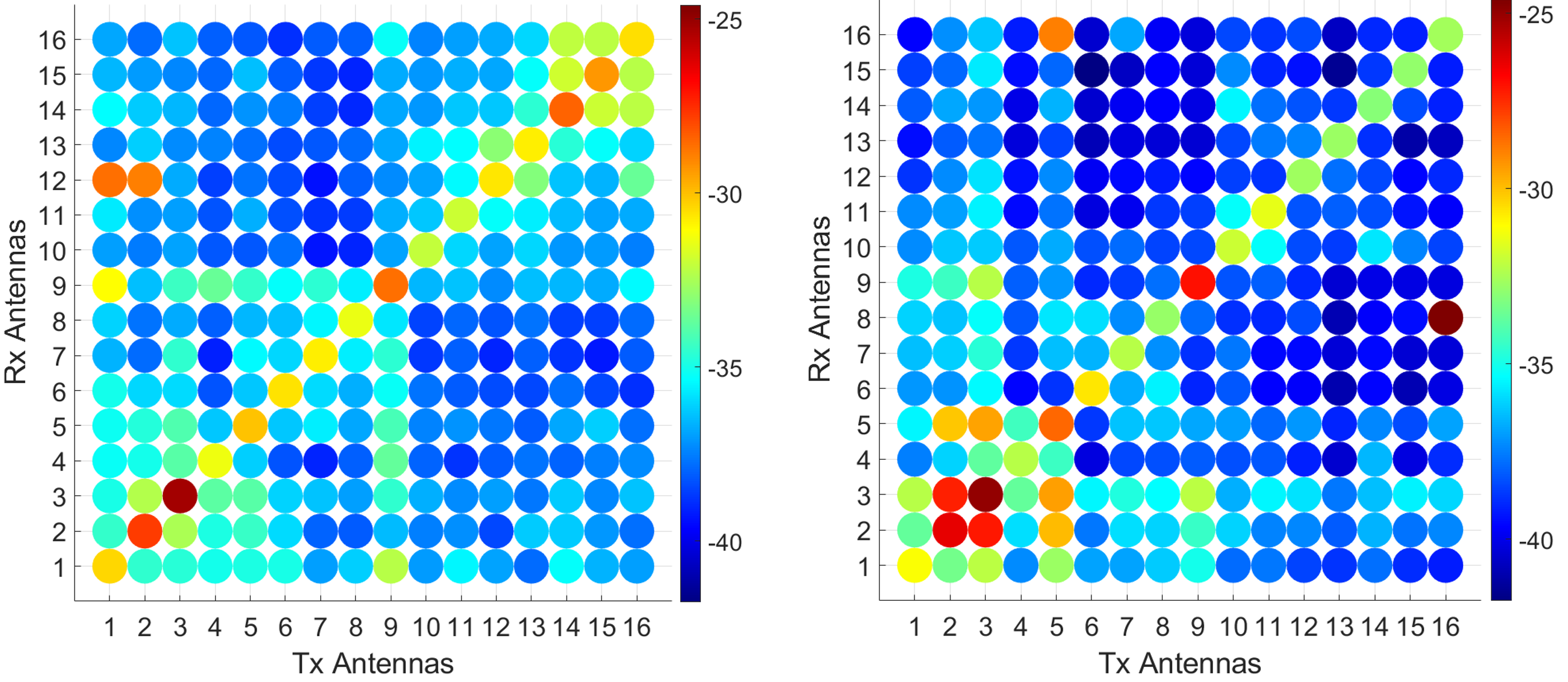
Reflection (Sii) and transmission (Sij) measurements were taken for each of the 16 antennas to all 16 others (16x16 measurements).
For more details of the measurement system, please see this paper or contact the authors.
Two datasets are provided. The first dataset is for the fat-only phantom with and without a tumor. The second dataset is for the skin-fat phantom with and without a tumor.
Matlab codes are provided to read each dataset, and report the detectable change for each antenna in the phantom with vs. without a tumor. This will create figures like Fig. 8 in the manuscript.
Format:
- Each dataset contains 512 files. Half of these 16x16=256 have a tumor, half do not. One dataset has a fat-only phantom. The other has a 2mm thick layer of skin-mimicking material on the outside of the phantom.
- Filenames are: Phantom_TransmittingAntenna_ReceivingAntenna
For example: FatOnly_A1T_A2R.mat has the data for the Fat-Only phantom (with no tumor) for Antenna #1 transmitting and Antenna #2 receiving.
- Inside each file are several columns:
- Column 1: Frequency (GHz) from 2-4 GHz
- Column 2: Sii (complex value)
- Column 3: Sji (complex value)
where i is the transmitting antenna, and j is the receiving antenna
Dataset Files
- Data_FatOnlyPhantom_TumorNoTumor.zip (2.91 MB)
- Data_Fat&SkinPhantom_TumorNoTumor.zip (2.91 MB)
- AvgMagnDiff_S11Tx_Fat.m (3.75 kB)
- AvgMagnDiff_S11Tx_Skin.m (1.84 kB)
Documentation
| Attachment | Size |
|---|---|
| 180.93 KB |


