Mobile stations KPI before and after RET optimization

- Submission Dates:
-
to
- Citation Author(s):
- Submitted by:
- Naran Khokshanov
- Last updated:
- DOI:
- 10.21227/s8p6-0f81
- Categories:
Abstract
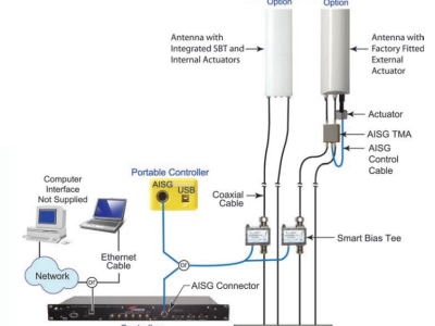
The dataset is intended to cover core issues pertaining to the area of a traffic optimization via RET motors inside the antenna on the mobile base station system (BSS). The principle of RET operation was already known to scientists; however, the use of a machine learning and big data provides the possibility of creation an autonomous system, which control RET system. The goal of the proposed research is to establish a new base to automatically remotely control RET for the BSS, by means of using machine learning, that as result permit to increase average speed in downlink for 1 user equipment (UE). As for the functionality, it focuses on the following three aspects: firstly, upload KPI from the main station (where occurs the change electrical angle) and from her neighboring, secondly, upload records after changing electrical angel, finally, collated records establish basis for new research and combined in one table. However, the proposed dataset contains records only LTE. The obtained results will serve as a basis for future works in the traffic optimization by dint of RET, insofar as the decreasing electrical tilt of antenna, we reduce serving are BSS, reduce the number of UE's and eventually increase average speed in DL for 1 UE's.
Instructions:
It is a simple Excel file. Each mobile base stations forms six-eight record per day (every 3-4 hours). The dataset has been collected during two time periods.
All table rows are following:
(A) - date in yyyy/mm/dd and hh/ss format.
(B) - order number in technology/number of base station/before - 1 and after - 2 changing electrical tilt. "Technology" - name of the used technology. For example, 081 - LTE800, 021 - LTE2600, 051 -LTE2100, 031 - LTE2300. "Number of base station" (BS) from 1 to 6, where 1 - BS with intalled extra technology, 2 - 6 neighboring BS.
(C) - average CQI, the smaller is value, the worse is modulation. As a result, the lower is average speed for 1 UE's.
(D) - average CQI of UE's that support 256 QAM, (D) less than (C).
(E) - average number of UE's connected via RRC protocol (a layer 3 (Network Layer) protocol used between UE and Base Station) to BS.
(F) - average cell downlink throughput(kbit/s).
(G) - average cell uplink throughput(kbit/s).
(H) - the downlink traffic sum that passed through the cell per hour (Mbit).
(I) - the uplink traffic sum that passed through the cell per hour (Mbit).
(J) - average speed for 1 UE's downlink (kbit/s)
(K) - average speed for 1 UE's uplink (kbit/s)
(L) - the measurement time interval. 1 - the first base station claster before changing electrical tilt. 2 - the first base station claster after changing electrical tilt. 3 - the second base station claster before changing electrical tilt. 4 - the second base station claster after changing electrical tilt.


