Datasets
Standard Dataset
Inertial Sensor Data from Healthy Adult Upper Limb Movements
- Citation Author(s):
-
MhairiMcInnes
 University of Aberdeen
 - Submitted by:
- Mhairi McInnes
- Last updated:
- Fri, 10/11/2024 - 05:47
- DOI:
- 10.21227/q4np-m373
- Data Format:
- License:
 497 Views
- Categories:
- Keywords:
Abstract
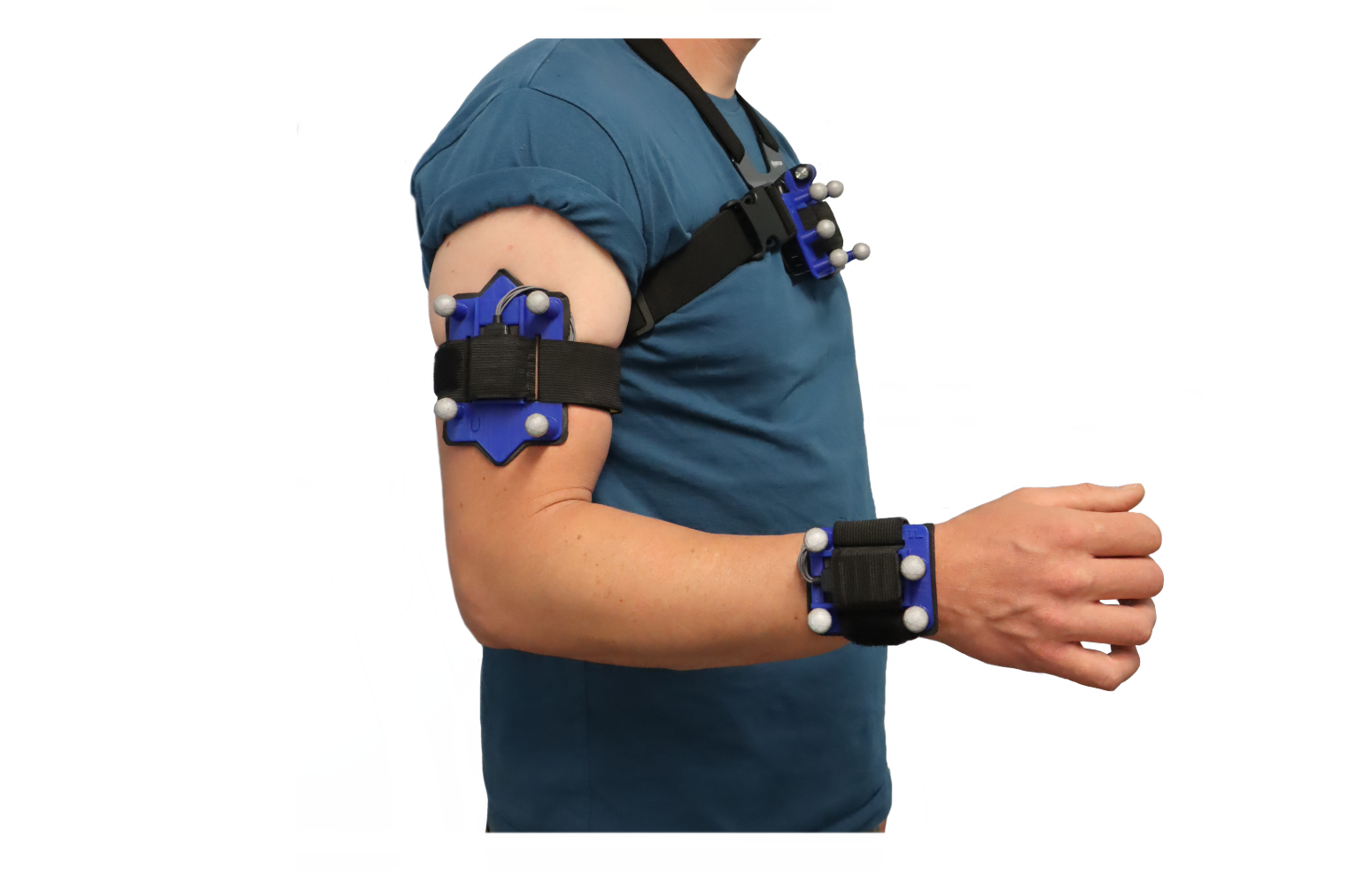
This dataset contains inertial sensor and optical motion capture data from a trial of 20 healthy adult participants performing various upper limb movements. Each subject had an IMU and cluster of relfective markers attached to their sternum, right upper arm, and right forearm (as in the image attached), and IMU and marker data was recorded simultaneously. This trial was carried out with the intention of investigating alternative sensor-to-segment calibration methods, but may be useful for other areas of inertial sensor research. CAD files for the 3D printed mounts are also included.
File Names
Each .txt data file is named with three types of information:
- Subject code - the numeric code associated with that individual, e.g., P001
- Trial name - the name assigned to the specific task/tasks which were carried out during that specific recording, e.g., ADL
- Data type - the type of recorded data, of which there are three options:
- Report 1 - Marker_Traj - This is the 3D position (or trajectory) data associated with the reflective markers and bony landmarks of the subject
- Report 2 - IMU_Quats - This is the quaternion orientation data measured by each IMU (IMU1: Thorax, IMU2: Humerus, IMU3: Forearm)
- Report 2 - Cluster_Quats - This is the quaternion orientation data associated with each cluster of reflective markers, and can represent 'perfect' IMU data
Participant metadata is aso included.
Movement Trials
Details of the movements found in each trial are as follows:
- CP ('Calibration Poses') - The subject performed a sequence of poses and motions intended for a pose-based S2S calibration. For each pose, the subject first performed the pose independently, then performed the pose with some feedback from the operator. The poses were performed in the following order:
- Neutral Pose - Upright, arms by side, elbow straight, thumb pointing forward
- Alt Pose - From neutral pose, bring elbow up to 90 degrees, thumb pointing up
- Alt2 Pose - From Alt Pose, flex shoulder forward to 90 degrees (humerus horizontal), keeping elbow bent to 90 degrees
- JA_Slow ('Joint Angles Slow') - The subject isolated each elbow axis and each shoulder axis consecutively, performing 5 repetitions of each movement at a slow speed:
- Elbow flexion/extension
- Forearm pronation/supination
- Shoulder internal/external rotation
- Shoulder ab/adduction
- Shoudler flexion/extension
- JA_Fast ('Joint Angles Fast') - The subject repeated JA_Slow, at a faster speed
- ROM ('Range of Motion') - The subject isolated each elbow and shoulder axis, flexing or extending to their maximum range of motion:
- Full elbow extension
- Full elbow flexion
- Pronation
- Supination
- External shoulder rotation
- Shoulder abduction
- Shoulder flexion
- Shoulder extension
- ADL ('Activities of Daily Living') - The subject performed a series of functional tasks (sometimes with props, sometimes miming), for 5 minutes, at a self-selected speed. Tasks included (usually in this exact order):
- Taking hat off head
- Taking wallet out of back pocket
- Pouring kettle into a mug
- Drinking from a mug
- Opening a high cupboard
- Sitting on a stool and standing back up
- Moving an object from one surface to another
- Fine motor task (building children's toy K'nex)
- Folding laundry
Other Information
The data in these .txt files was created in a The Motion Monitor software, which time-synchronised the systems, and performed some filtering and repair to both the IMU and marker data.
Equipment:
- Delsys Trigno Quattro inertial sensors
- OptiTrack optical motion capture system
3D Printed Mounts
The CAD files for the humerus and forearm mounts are included in this dataset. The design of these mounts was chosen to be able to support both the reflective markers and the IMUs. More importantly, the design was chosen to maximise the chances of the IMUs aligning with the coordinate frame of the underlying bone segments.
The IMU recess dimensions are designed for Delsys Trigno Quattro sensors, but could be adjusted for different IMUs.
Manufacture guidance:
- 3D print orientation: cones pointing upwards
- Wide elastic straps were made (40mm) which run through the wide slots in the mounts, and wrap around the arm. One end can be permenantly fixed, the other can be tightened with velcro.
- The same strapping was used to hold the IMUs in place, fed through the slots in the mounts, and sewn until tight, so that the IMU can be pushed in and help down tight.
- Foam pads can be cut (3mm craft foam was used) which are slightly larger than the perimeter of the mounts, and glued to the underside, to make a more comfortable contact with the skin
- Foam rectangles were cut to fit inside the IMU recess which stopped the IMU slipping
Please feel free to contact me for more information.
Dataset Files
- P001.zip (19.81 MB)
- P002.zip (19.47 MB)
- P003.zip (19.18 MB)
- P004.zip (20.18 MB)
- P005.zip (19.13 MB)
- P006.zip (19.27 MB)
- P007.zip (22.41 MB)
- P008.zip (18.83 MB)
- P009.zip (19.99 MB)
- P010.zip (19.44 MB)
- P011.zip (20.89 MB)
- P012.zip (20.10 MB)
- P013.zip (18.75 MB)
- P014.zip (21.21 MB)
- P015.zip (20.48 MB)
- P016.zip (20.25 MB)
- P017.zip (19.61 MB)
- P018.zip (18.25 MB)
- P019.zip (18.17 MB)
- P020.zip (19.33 MB)
- Mount_CAD_files.zip (1.87 MB)
- Participant_MetaData.xlsx (12.92 kB)


