Datasets
Standard Dataset
Distributed Multi-User MIMO Datasets
- Citation Author(s):
- Submitted by:
- Mehdi Zafari
- Last updated:
- Wed, 09/18/2024 - 23:14
- DOI:
- 10.21227/74ez-b275
- Links:
- License:
 349 Views
- Categories:
- Keywords:
Abstract
We conducted a massive MIMO channel measurement and uplink multi-user data transmission experiment in an indoor setting on the Rice University campus. The original purpose of this dataset was to study the effect of placement of massive MIMO BS arrays on performance in two scenarios of co-located and separated (distributed) as well as the effect of phase coherence among the arrays during channel measurement and data transmission. Use the link to access the datasets.
Dataset Description
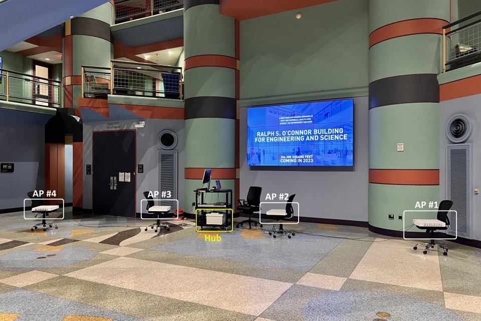
For our experimental setup, we used an indoor RENEW massive MIMO base station, equipped with four chains of Iris SDRs, consisting of 64 antennas in total. Each chain consists of 8 interconnected SDRs with dual-polarized antennas, forming a linear array that supports a total of 16 streams. All of these chains are connected to the central hub via a wired fiber link. These chains are considered as APs and are employed in two physical configurations: co-located and distributed. The clock signal in each AP is achieved through a daisy chain approach, where the initial SDR (head) of the chain disseminates the clock to all other SDRs in that AP. This clock at the head SDR can either be received from the hub (HUB-mode) or derived from the independent LO at the head SDR itself (LO-mode).
Co-Located: All four APs are stacked on top of each other, forming a 2D co-located 64-antenna massive MIMO array.
Distributed: APs are located 3 meters away from each other to emulate a physically distributed massive MIMO array.
HUB-mode: Perfect time and frequency are achieved via the hub.
LO-mode: The time trigger is shared by the hub, but each AP uses an independent LO, introducing a random CFO.
Users: Six standalone Iris SDRs are used as users, equally spaced on a circle with a diameter of 14m in an indoor hall. Each transmission attempt in each scenario was repeated twice, one on each of the UE RF chains (channel A & channel B).
Pilot and Data Symbols: We set up the frame schedule for the users so that each user sends time-orthogonal pilots and then all simultaneously transmit data OFDM symbols. We use the 802.11 LTS signal as the pilot symbol, which is used for channel estimation and beamforming matrix calculation. The format of the data OFDM symbols also follows the 802.11 standard, where the FFT size is 64. Out of the 64 subcarriers, 48 subcarriers carry data, 4 are pilot subcarriers, and the remaining are null subcarriers. Each uplink data slot includes 10 OFDM symbols. We try QPSK for modulating data subcarriers.
MIMO Configurations:
- 61x1: 5 combinations of users
- 61x2: 3 combinations of users
- 61x4: 4 combinations of users
- 61x6: 1 combinations of users


